


How deck space constraints affect marine crane installation
A constrained deck does not simply limit where a Marine Crane can be placed. It changes the installation strategy, the usable lifting envelope, the structural work below the crane, and often the vessel's day-to-day workflow. A crane that fits within an available footprint can still be the wrong choice if its slewing path blocks access, its foundation loads cannot be transferred properly, or its boom cannot reach the intended lifting zones without operating near its limits.
For a vessel owner, operator, or project manager, the practical objective is not to install the largest crane that can physically be brought aboard. It is to create a lifting arrangement that delivers the required loads at the required radii while preserving safe access, vessel stability, maintainability, and operational space.
Deck area is only the starting point
Installation drawings often begin with the crane pedestal footprint. That is necessary, but it is not enough. The real space requirement includes the crane's rotating structure, boom stowage position, hook travel, operator access, maintenance clearance, hydraulic connections, electrical routing, and nearby walkways.
A compact base can be misleading. During slewing, the crane's counterweight, boom, hook block, or suspended load may enter areas used for cargo handling, mooring, hatch access, emergency routes, or equipment servicing. These conflicts are especially common on workboats, offshore support vessels, fishing vessels, dredgers, and retrofits where the deck already has a defined operating layout.
The decision should therefore be based on an operating-space study rather than a footprint dimension alone. Map the crane through its expected motions, including boom parking, full slewing where applicable, typical lifts, and abnormal but foreseeable positions such as hook retrieval and maintenance access.
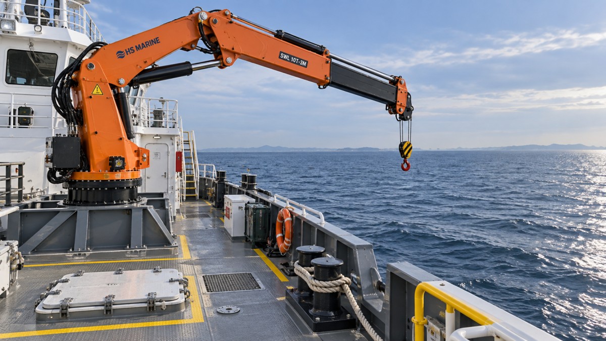
The foundation may consume more space than the crane
Deck space constraints frequently become structural constraints. A Marine Crane transfers vertical load, overturning moment, and dynamic forces into the vessel structure. The deck plating beneath a pedestal is rarely the entire answer; the load path may need to continue through stiffeners, girders, bulkheads, or supporting structure below deck.
When the preferred crane location is above accommodation, machinery spaces, tanks, cable routes, or other crowded compartments, reinforcing the structure can become difficult and expensive. Moving the crane a short distance may simplify the foundation substantially, but it may also reduce working radius or create access conflicts. This is why crane location and structural design must be assessed together, not sequentially.
A common mistake is to treat reinforcement as a local steelwork task after the crane model has been selected. By then, the selected unit may require intrusive modifications below deck, reduce tank access, or interfere with existing systems. Early structural review can reveal whether a slightly lighter crane, a different pedestal height, or a revised lifting position provides a more workable result.
Limited deck space changes the capacity decision
Rated capacity alone does not describe whether a crane can perform the lift. The required capacity must be checked at the actual outreach, with allowance for the hook, rigging, lifting attachments, and the vessel's operating condition. On a tight deck, the crane cannot always be positioned at the ideal location, so it may need to reach farther than expected. That is where available lifting capacity typically reduces.
Decision-makers should define the lift in practical terms: the heaviest item, where it is picked up, where it is set down, the normal and maximum working radius, the required lift height, and whether the vessel may be moving. A crane selected only for its maximum nominal load can become inefficient when its capacity at the needed radius is insufficient.
Compactness may also require compromises. A folding or knuckle boom can reduce stowage intrusion in some layouts, while a straight boom may offer a simpler working geometry for certain lifts. Neither arrangement is automatically better. The right configuration depends on the obstruction pattern, required reach, available headroom, cargo path, and whether the crane must work over the side, across an open deck, or into a defined loading area.
Access and operations cannot be treated as spare space
On vessels with restricted deck area, every installation competes with a working route. A crane placed near a rail may improve over-side reach but obstruct mooring activity. A central position may improve lifting coverage but divide cargo space or interfere with hatch openings. A location close to machinery may shorten hydraulic runs but make routine maintenance more difficult.
The important question is not “Where is there empty deck?” It is “Which activities must continue when the crane is parked, operating, and under maintenance?” Review the location with deck crews, maintenance personnel, and those responsible for cargo or mission equipment. Their input often identifies practical conflicts that are absent from a general arrangement drawing.
Clear access is also needed for inspections, lubrication, hose replacement, wire-rope handling where relevant, and recovery from a fault condition. A crane that can only be serviced after removing adjacent equipment or suspending deck operations creates a long-term operating cost that may outweigh the benefit of a convenient initial location.
Slew limits can be a better solution than a compromised location
When full rotation would sweep into occupied areas, it may be preferable to define a controlled working sector rather than force the crane into an inferior position. Slew restriction can protect accommodation structures, antennas, exhaust systems, cargo routes, or hazardous areas from the crane and its load.
That approach works only when the permitted sector still covers every required lift with adequate radius and boom clearance. It should be evaluated as part of the lifting plan, not added as an afterthought. A restricted slewing envelope also affects where loads can be landed and how rigging personnel can work safely around the crane.
For installations where equipment must be moved between vessel decks and quayside support areas, a mobile deck-handling arrangement may sometimes be considered alongside a fixed marine unit. For example, the Straight Boom FST6.3E3 is a truck-mounted straight-boom crane with 360-degree endless slewing, a stated maximum capacity of 6.3 tonnes, and outreach up to 12.64 m. Its data may be useful as a reference for shore-side or dockside handling planning, but it should not be assumed to be a substitute for a purpose-designed Marine Crane installation on a vessel.
A practical review sequence before approving the installation
Deck constraints are best managed before procurement, when location and configuration options are still open. The following sequence keeps the decision focused on actual lifting performance rather than available floor area:
- List the required lifts. Include load weights, pick and set-down points, lifting frequency, required radii, and whether lifts occur over side or within the deck area.
- Create an operational deck map. Mark cargo routes, hatches, mooring stations, escape paths, equipment access points, and areas that must remain clear.
- Test crane envelopes. Review pedestal footprint, boom stowage, slewing sweep, hook path, and the load path through the full intended operating range.
- Assess the supporting structure. Confirm that the foundation concept has a realistic load path through the vessel without unacceptable interference below deck.
- Check service requirements. Reserve space for inspection, repair, hoses, controls, and safe personnel access before finalizing the layout.
- Review stability and operating limits together. The crane, vessel condition, anticipated sea state, and lift procedure must be treated as one operating system.
When a smaller crane is not the lower-risk option
Choosing a smaller unit can free deck space and reduce foundation demands, but it is not automatically the safer commercial choice. If it forces routine lifts to occur at the edge of the load chart, requires repeated repositioning of cargo, or cannot cover an expected future task, the apparent saving may be lost through slower operations and restricted capability.
Conversely, an oversized crane can create a heavier foundation, larger exclusion zones, higher interference risk, and unnecessary installation complexity. The best selection is usually the smallest configuration that can complete the defined lift profile with suitable margin and without disrupting essential deck operations.
Before approving a Marine Crane layout, ask for the operating envelope, foundation load information, and a deck arrangement showing how the crane coexists with normal vessel activities. That review turns “limited deck space” from a late-stage installation problem into a controlled design decision.
Send Us A Message
Get a Quote
Regardless of whether you require general advice or specific support, we are happy to help you.