


How outrigger footprint affects truck mounted crane site selection
Outrigger Footprint Is a Site-Selection Issue, Not Just a Setup Detail
Selecting a safe position for a Truck Mounted Crane starts well before the operator deploys the outriggers. Load weight, working radius, and ground condition are obvious checks, but the physical area occupied by the stabilizers is often what decides whether a proposed lifting point is actually usable. A location may look suitable from the cab or from a basic site drawing, yet become unworkable once the outriggers need to extend across a traffic lane, near a trench edge, into a pedestrian route, or onto ground with mixed support conditions.
For quality and safety teams, the outrigger footprint should be treated as part of the crane’s operating envelope. It affects not only stability during the lift, but also exclusion-zone planning, underground-service exposure, access for other trades, and the ability to maintain the crane in a level condition. The practical question is not simply, “Can the truck park here?” It is, “Can the truck be stabilized here for the full intended lifting range without creating a new risk?”
What the Outrigger Footprint Actually Changes
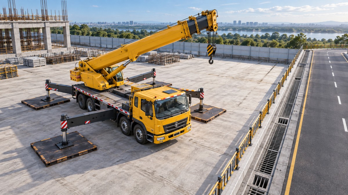
The footprint is the area created by the deployed outriggers, support pads, and any timber or engineered mats used beneath them. On many jobs, this area is much wider than the vehicle body. A narrow service road may accommodate the truck itself, for example, while leaving no room for a fully extended stabilizer on one side. That is not a minor inconvenience. Reduced outrigger spread can change the crane’s permitted lifting capacity, depending on the manufacturer’s load chart and stabilizer configuration.
A wider spread generally provides a larger and more stable support base, but it also demands more clear ground. The site planner must reserve room for the outrigger beams, jacks, pads, and the personnel who inspect them. Clearance is particularly easy to overlook beside building walls, stored materials, temporary fencing, open drains, parked vehicles, and scaffold legs. A crane may have enough room to deploy, yet insufficient room to allow a rigger to safely check pad contact or observe movement during the initial load pick.
The support footprint also determines how crane forces are introduced into the ground. The load is not spread evenly across the entire parking area. It is concentrated at the outrigger contact points, and the highest reaction may occur at a particular stabilizer depending on boom direction, radius, load position, and slew angle. Looking only at whether the pavement appears solid is not enough.
Ground Bearing Pressure: The Detail That Can Defeat a Good-Looking Site
Hardstanding can be misleading. Asphalt may look intact while covering weak fill, voids, recently backfilled utility trenches, drainage channels, or a slab not designed for concentrated crane reactions. Likewise, compacted soil can appear firm in dry weather and lose capacity after rain. Quality checks should identify both the visible surface and what is known about the layer beneath it.
The basic relationship is straightforward: ground pressure rises when the same outrigger force is carried over a smaller contact area. Pads and mats can reduce pressure by increasing that area, but they do not automatically make unsuitable ground safe. They must be properly sized, placed on stable and reasonably level support, and capable of distributing the load without cracking, rocking, or bridging over a void. Stacking loose blocks, using damaged timber, or placing a mat partly over an edge should be rejected rather than accepted as a field adjustment.
For illustration, the published figures for the truck-mounted Straight Boom FST3.2E3 include a maximum ground pressure of 2.8 MPa with fully extended ST outriggers and 2.2 MPa in the EX configuration. Those values are crane-specific operating data, not a declaration that every concrete yard, roadway, or compacted work area can safely accept the load. The actual site decision still depends on the support surface, pad area, subsurface information, and the applicable lift configuration.
Site Constraints That Need to Be Marked Before the Crane Arrives
A worthwhile pre-lift review maps the deployed footprint, not just the truck parking position. On a crowded project, that map often reveals conflicts early enough to change delivery timing, crane orientation, or the loading point. It is far easier to move a pallet drop zone on paper than to improvise after a crane has blocked the only emergency access route.
- Trench lines, manholes, culverts, basement edges, retaining walls, and recently reinstated ground.
- Overhead lines, building projections, scaffold ties, awnings, and boom-swing obstructions.
- Vehicle routes, fire lanes, pedestrian walkways, and access required by other contractors.
- Slopes, crossfalls, soft shoulders, kerbs, and changes between pavement and unpaved ground.
- Space for mats, rigging activity, spotters, and a controlled exclusion zone around the lift.
Edges deserve special attention. An outrigger pad placed near the edge of an excavation, slab, embankment, or drain can transfer force into ground that is less capable of resisting it. There is no universal safe stand-off distance that can be applied without reference to excavation depth, soil condition, support design, and local requirements. When uncertainty exists, the right response is to obtain competent engineering or project guidance, not to rely on the fact that a previous vehicle parked nearby.
Why Full Extension Cannot Be Assumed
A common planning error is to select a site using the crane’s maximum rated capacity, then discover that one outrigger cannot be fully extended because of a wall, lane boundary, or obstacle. Some crane designs permit defined intermediate outrigger positions, but their allowed lifting capacities and operating sectors may differ substantially from the fully extended arrangement. The operator must work from the correct load chart and configuration information; the site team should not make a casual decision to “bring one side in a little.”
Asymmetric setups need even more care. A vehicle may be physically level while the available support width differs from one side to the other. This can affect permissible slewing sectors and the operational margin during a pick. A site may therefore be acceptable for a lift made toward open ground but unacceptable for a similar load handled over the restricted side. The intended load path matters as much as the delivery point.
A Better Method for Reviewing the Proposed Crane Position
The most reliable process is to review the lift from the ground up. Confirm the load and radius, then identify the required stabilizer configuration from the crane documentation. Mark the approximate outrigger positions on the site plan or directly on the ground. Check clearances, surface changes, underground features, and the room needed for mats. Only then should the team confirm boom direction, slew path, and exclusion arrangements.
Before lifting, verify that all outriggers have positive, stable contact and that the chassis is level in accordance with the crane manufacturer’s instructions. Recheck after the first controlled pick. Settlement, pad rotation, cracking of the support surface, or a visible change in level should stop the operation for reassessment. Small movement at an outrigger can become significant when the boom is extended and the load is suspended.
Quality control records are most useful when they capture the conditions that can change: weather, pad or mat arrangement, outrigger extension, ground observations, nearby excavation work, and any deviation from the original plan. A generic “ground checked” note does little to explain why a location was accepted. A brief, specific record makes later review more defensible and helps prevent the same assumptions being repeated on the next lift.
The Practical Site-Selection Test
A suitable Truck Mounted Crane location is one where the crane can be parked, fully supported in its approved configuration, kept level, and operated through the planned load path without compromising people, access, or ground integrity. If any of those conditions depends on an improvised pad stack, a blocked traffic route, an unverified trench crossing, or an assumed partial-outrigger rating, the location is not ready.
The outrigger footprint turns site selection into a three-dimensional planning exercise: support beneath the crane, clearance around it, and safe movement above it. Treating that footprint as a fixed design input rather than an on-the-day adjustment is one of the clearest ways to prevent avoidable lifting setup errors.
Send Us A Message
Get a Quote
Regardless of whether you require general advice or specific support, we are happy to help you.