


A 10Ton Steel Track Spider Crane can be suitable for uneven ground, provided its travel limits, outrigger arrangement, ground support, and lifting configuration match site conditions.
Steel tracks alone do not establish safe lifting conditions. Technical evaluators must assess access to the work area separately from stability during the planned lift.
The decisive questions concern allowable slope, ground bearing capacity, outrigger reactions, permitted leveling arrangements, and the load chart applicable to the actual working radius and configuration.
This assessment should establish whether the crane can reach its position, create a compliant lifting setup, and complete the required lift without exceeding manufacturer limits.
Can it reach the site and establish a level lifting position?
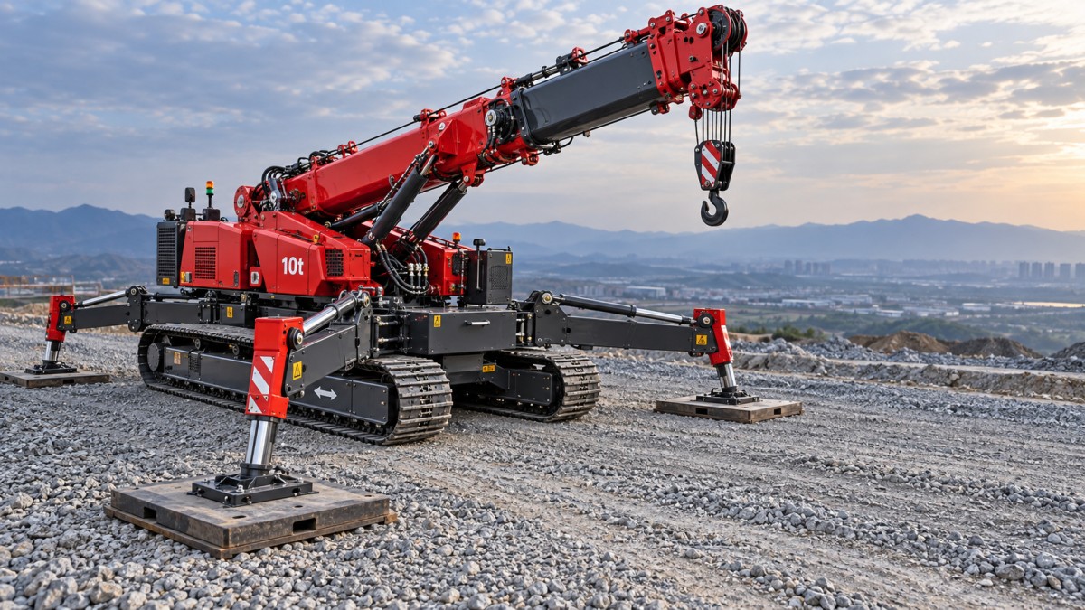
Uneven ground presents two separate challenges: traveling across irregular terrain and supporting a stationary crane under load. Successful travel does not demonstrate suitability for lifting.
Tracked travel may help distribute machine weight and negotiate some surface irregularities, but performance depends on track dimensions, ground conditions, gradient, and the manufacturer's operating limits.
Check longitudinal gradeability and permitted cross slope separately. A stated climbing capability must never be interpreted as permission to traverse that same gradient sideways or lift.
Inspect transitions as well as average slope. Ruts, abrupt crests, trenches, and isolated rocks can alter contact conditions, reduce clearance, or destabilize the traveling machine.
For lifting, the outriggers must establish the level condition specified by the manufacturer. Do not assume that long outrigger strokes allow operation on any slope.
Request documented travel limits, required boom position, ground clearance, and allowable lifting inclination. If these are unavailable, the machine's suitability for the proposed terrain remains unverified.
Will the ground support the most heavily loaded outrigger?
Ground support often determines feasibility before lifting capacity does. A firm surface can conceal weak fill, saturated soil, underground services, culverts, or an unsupported slab.
Obtain allowable ground bearing pressure from an appropriate site assessment. Surface appearance, previous vehicle access, and nominal crane weight cannot reliably establish this value alone.
Ask the supplier for maximum outrigger reactions relevant to the proposed lift. Reactions vary with boom position, load, counterweight, outrigger geometry, and permitted operating sector.
Do not estimate each reaction by dividing total weight equally between four outriggers. During lifting, one support can carry substantially more load than the others.
A preliminary bearing area is calculated as outrigger reaction divided by allowable ground pressure. Use consistent units, then have suitable personnel verify the complete support arrangement.
For example, a 120 kN reaction on ground allowing 100 kPa requires 1.2 square meters of effective bearing area before accounting for other design considerations.
That calculation does not specify a finished mat. Mat stiffness, bending resistance, contact conditions, edge distances, and load distribution through the underlying ground also require assessment.
Can the outriggers level the crane within an approved configuration?
Measure the proposed setup area rather than describing it simply as uneven. Record elevations at support locations, local obstructions, available footprint, and nearby excavation edges.
Confirm whether the outriggers can reach suitable bearing locations while maintaining the manufacturer's required extension, geometry, pad contact, and leveling range throughout the planned operation.
Variable outrigger positioning is useful only when the manufacturer permits it. Restricted extension may require a different capacity chart or limit the available lifting sector.
Likewise, different support elevations do not automatically invalidate a setup, but they require an approved arrangement that maintains machine level and properly supports every outrigger.
Use engineered mats or approved cribbing where required. Loose packing, unstable stacks, and unsupported mat edges can introduce movement even when initial level readings appear acceptable.
Check level after setup and monitor for settlement as required by the operating procedure. Stop if support movement or inclination exceeds the manufacturer's permitted limits.
Does the load chart cover the actual lift?
The description “10-ton” identifies a capacity class, not a lifting capacity available at every radius. Maximum capacity normally applies only under specific, favorable chart conditions.
Evaluate the heaviest required load at its greatest working radius, using the manufacturer's radius definition. Include the pickup position, travel path of the load, and placement position.
Account for slings, shackles, lifting beams, and other accessories according to the chart instructions. Confirm whether the quoted capacity requires deductions for hook equipment or attachments.
Match the chart to boom length, jib arrangement, counterweight, outrigger extension, operating sector, and specified level condition. A chart from another configuration cannot establish suitability.
If the crane must reposition between lifts, assess each setup independently. A suitable initial position does not validate another location with different support conditions or radius.
Wind and load shape also matter. Large panels may create handling restrictions even below the weight limit, so follow documented wind and projected area requirements.
What can product specifications establish—and what remains unproven?
Product comparisons require careful classification. A knuckle boom crane specification does not establish the performance of a complete tracked spider crane assembled around that lifting unit.
The HB250 is identified in the supplied specifications as a knuckle boom crane, with listed design standards EN 12999 and DIN 15018 and radius dependent capacities.
Its stated rated lifting capacity is 9,580 kg at 2.55 meters, falling to 965 kg at 15.92 meters. These figures illustrate the importance of radius.
Those specifications do not establish tracked travel limits, complete machine stability, or suitability for uneven ground. Evaluators need documentation for the actual assembled crane being offered.
The listed maximum outrigger ground contact pressure of 3.70 MPa must also be clarified. It cannot directly replace site bearing capacity data or configuration specific reactions.
Likewise, the listed 3,000 kg weight excludes outriggers. It should not be treated as the operating mass of a complete tracked machine during access planning.
Which site conditions require preparation or another lifting arrangement?
Uneven terrain may be manageable when competent ground, adequate setup space, and approved leveling arrangements are available. Some sites require preparation before a crane becomes suitable.
Soft fill, waterlogged ground, uncertain buried structures, and locations close to excavations require further assessment. Larger mats alone may not resolve deeper ground failure mechanisms.
A steep access route may prevent the machine reaching otherwise suitable lifting ground. Route grading, temporary access works, or a different crane position may be necessary.
Restricted outrigger space can make a nominally powerful crane unsuitable. Compare the permitted capacity for the available footprint against the entire lift, including placement radius.
Changing weather can invalidate an earlier assessment. Rain, thawing ground, erosion, or water accumulation may reduce support quality and require inspection before work resumes safely.
Where compliant support cannot be demonstrated, consider engineered ground improvement, another setup location, or different lifting equipment. Record the resulting access and capacity requirements explicitly.
How should technical evaluators make the final decision?
Approve a 10Ton Steel Track Spider Crane for uneven ground only when documented access limits, support conditions, leveling capability, and lifting capacity all cover the planned operation.
The assessment should combine a measured site survey, ground bearing information, configuration specific outrigger reactions, the applicable load chart, and manufacturer instructions for setup and travel.
Record unresolved information as a condition requiring verification. A supplier's general claim of rough terrain capability cannot substitute for evidence covering the actual site and lift.
The practical conclusion is conditional: uneven ground can be workable, but suitability depends on establishing a supported, level lifting configuration within every relevant manufacturer limit.